Whether you are building a road base over soft soil, stabilizing a commercial parking lot with continuous vehicular traffic or reinforcing the subgrade of an industrial platform, the biaxial geogrid is the component that separates a project that lasts for decades from one that shows deformation within a few months. This MOLTEXO PP biaxial geogrid delivers 40 kN/m of bidirectional strength in a 6 m × 50 m roll, a dimension calibrated to roll out without cuts on most road and platform projects. This guide explains the correct procedure for rolling out, overlapping, fastening and backfilling so that the grid provides the bearing capacity calculated in the project design.
The installation procedure is simple but strict: insufficient overlap at joints, incorrect roll orientation or poor aggregate compaction can cancel out up to half of the designed structural capacity. Read it in full before starting the rollout: the difference between a successful project and one that shows potholes within the first year is almost always in the installation technique, not in the quality of the grid.
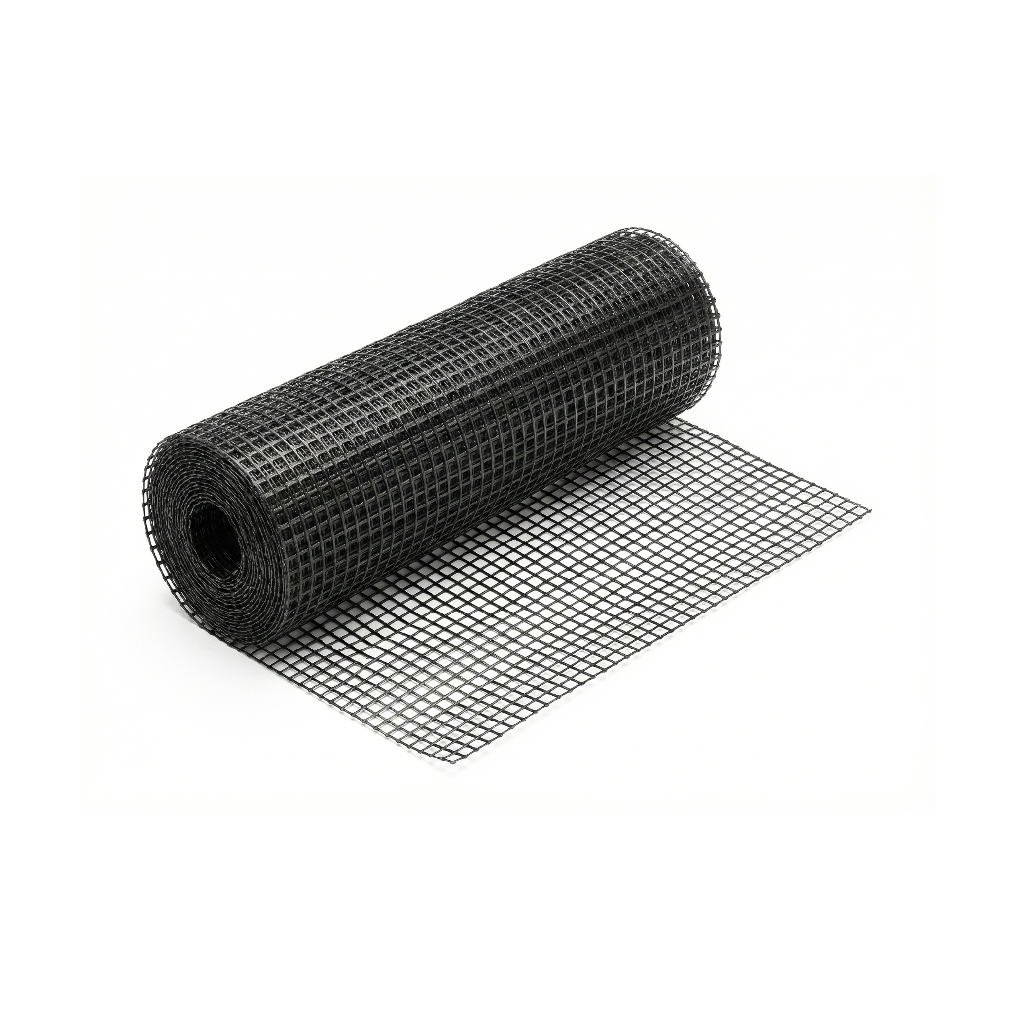
Product specifications
The polypropylene biaxial geogrid is offered in a single standard presentation of 6 m wide by 50 m long, with auditable bidirectional strength of 40 kN/m. The following table sets out the complete technical specifications of the only available variant:
| Specification | Value |
|---|---|
| SKU | 561774 |
| Material | Virgin extruded polypropylene (PP) |
| Orientation type | Biaxial (stretched in two directions) |
| Tensile strength | 40 kN/m (2.74 kip/ft) in both directions |
| Aperture shape | Rigid square/rectangular |
| Roll width | 6 m (19.7 ft) |
| Roll length | 50 m (164 ft) |
| Area per roll | 300 m² (3229 ft²) |
| Chemical resistance | Inert to acids, alkalis and soil microorganisms |
| Estimated service life | Decades under buried conditions |
| Main application | Horizontal reinforcement of bases and subgrades |
| Color | Black (with anti-UV carbon black additive) |
The sister guides for the PP uniaxial geogrid and the PP triaxial geogrid cover the other two orientations in the family: the uniaxial is specifically designed for MSE walls and slopes (directional loads with low creep), and the triaxial delivers omnidirectional confinement optimized for very soft subgrades or complex vehicular traffic.
Step-by-step use
The following procedure covers the complete on-site installation cycle: from subgrade preparation to compaction of the aggregate over the grid. Supervision by a geotechnical engineer or qualified site engineer is always recommended on structural projects; the following indications are for guidance only and do not replace the project-specific engineering design.
Subgrade preparation
Clear the surface of roots, large stones and vegetation. The subgrade must be leveled (no potholes larger than 5 cm) and compacted to the minimum density specified in the project. Avoid rolling out the geogrid over water-saturated soil: if after rain the subgrade shows surface water, drain it or wait until it dries partially. A geogrid rolled out over mud provides no reinforcement because the aggregate matrix cannot be confined correctly.
Rolling out the roll
Unroll the roll in the longitudinal direction of the project (road axis, platform axis). The direction is relatively free because the biaxial grid works in two directions, but it is advisable to keep visual consistency throughout the project. Keep the grid taut during rollout —folds and wrinkles reduce the aggregate confinement effect—. If you need several rolls, align them so that the joints are perpendicular to the main expected direction of traffic.
Overlapping at joints
When joining two rolls, overlap a minimum of 30 cm at longitudinal joints and 50 cm at transverse joints (that is, in the main direction of traffic). For very soft subgrades (CBR below 3), increase the transverse overlap to 1 meter. The rule of thumb: if the subgrade sinks when you step on it, the overlap must be greater. Never cut the grid to "make use of" a remnant at joints; always do it with continuous overlap.
Temporary fastening with anchors
Use metal rods or J-shaped fastening staples every 1-2 meters to keep the grid in position during the backfilling operation. The fastening is temporary —its sole purpose is to prevent the grid from shifting when the machinery passes with the aggregate—. For large rollouts in windy conditions, add sandbags or large stones along the edges.
A field trick to verify that the overlap is correct: have a worker walk over the joint before backfilling, without compaction, and observe whether the grid lifts or shifts. If it moves more than 2-3 cm, increase the overlap or add anchors. Doing this check with personnel before bringing in the machinery reveals rollout problems that are irreparable after compaction.
Backfilling and compaction
Dump the aggregate onto the grid WITHOUT DRIVING machinery directly over the exposed geogrid. Keep at least 15 cm of aggregate between the tracks or wheels and the grid. Spread the aggregate in layers of no more than 30 cm and compact each layer to the Proctor percentage specified in the project before spreading the next one. Compaction is where the mechanical confinement provided by the grid is "activated" —poorly compacted aggregate does not interlock with the grid and the investment is nullified—.
Do not use biaxial geogrid where the project calls for uniaxial (MSE walls, slopes of considerable height, abutments). The biaxial has moderate bidirectional strength and low creep resistance under sustained load. In an MSE wall several meters high, a 40 kN/m biaxial instead of an 80 kN/m uniaxial can deform progressively over the years until collapse. The biaxial vs uniaxial vs triaxial selection is NOT optional or interchangeable: it depends on the direction and type of load calculated by the structural engineer.
Complementary products
To complement the biaxial geogrid in road base and subgrade reinforcement projects, the following products cover the most common adjacent needs during design and installation:
The PP triaxial geogrid is the higher-performance alternative for very soft subgrades or heavy vehicular traffic: the triangular geometry confines the aggregate in three directions and allows the backfill thickness to be reduced even further compared to the classic biaxial. The PP non-woven geotextile is installed as a separation layer beneath the biaxial geogrid when the subgrade consists of fine particles (silts, clays) that can contaminate the aggregate through fines pumping during operation. The metal rods are used as temporary anchoring of the geogrid during rollout and before the first backfill. The PP uniaxial geogrid is the specific solution when the project includes MSE walls or slopes that require high directional strength and low creep.
Maintenance and care
Geogrids require no maintenance during their service life because they are designed to remain buried beneath a layer of aggregate and pavement. The relevant care concerns storage and handling prior to installation: the rolls are stored in a horizontal position, covered for protection from direct sunlight (although the PP carries an anti-UV additive, prolonged storage in the sun degrades the surface properties) and on a clean surface that does not puncture the original packaging.
During handling on site, avoid dragging the rolls over stones or metal with sharp edges that could tear the roll before rollout. A 30 cm transverse cut in a full roll significantly reduces the usable area of the product, because of the affected zone and the adjacent material that also provides no reinforcement. Visually inspect each roll before rolling it out, especially the edges that may have been struck during transport.
Frequently asked questions (FAQ)
What minimum overlap should I use at joints?
For subgrades in good condition (CBR above 5), 30 cm at longitudinal joints and 50 cm at transverse joints are sufficient. For soft subgrades (CBR between 1 and 3), increase the transverse joints to 75 cm or 1 meter. For very soft or swampy subgrades (CBR below 1), consider using a more resistant geogrid or adding a separation geotextile beneath the grid. Joints with insufficient overlap are the main cause of localized potholes in pavements with apparent geogrid.
Can I use the biaxial geogrid over water-saturated soil?
Technically yes, but performance will be limited: the aggregate cannot be confined correctly over saturated mud, and the effect of the grid is greatly reduced. If the project requires rolling out geogrid over saturated soil, add a layer of non-woven geotextile beneath the grid for separation and filtration, and consider an additional layer of coarse drainage aggregate. The ideal is still to drain the soil before installing.
How many m² does a roll cover and how many rolls do I need for my project?
A 6 × 50 m roll equals 300 m² of nominal coverage. To calculate the actual number of rolls, add the overlap: on a standard project, an efficiency of 85-90% is realistic (10-15% is "lost" in overlaps and edge cuts). For a 1000 m² platform, calculate between 3.7 and 4 rolls. If the project has irregular shapes or frequent changes of direction, reserve an additional 5-10% for on-site adjustments.