If the classic biaxial geogrid does not deliver the expected performance on your road project over soft soil —that is, if plate load tests or field trials show residual settlement greater than allowable under dispersed vehicular loads— the triaxial geogrid is the highest-performance option in the family for horizontal reinforcement. This MOLTEXO triaxial PP geogrid delivers 10 kN/m with an extended geometric structure in three directions (0°, 60°, 120°) and rigid triangular apertures, in a 3.95 m × 50 m roll. The difference from the biaxial lies in how it confines the aggregate: the triangular apertures work more efficiently on crushed stone and gravel under multidirectional loads than traditional square apertures.
The installation procedure is similar to that of the biaxial —rolling out, overlap, temporary fixing and layered backfill— but with two relevant operational differences: the roll is narrower (3.95 m vs 6 m for the biaxial), so the roll-out planning changes, and aggregate confinement is activated with less initial compaction thanks to the triaxial geometry. This guide explains the operational differences compared to the biaxial and when it is justified to use triaxial instead of the standard biaxial.
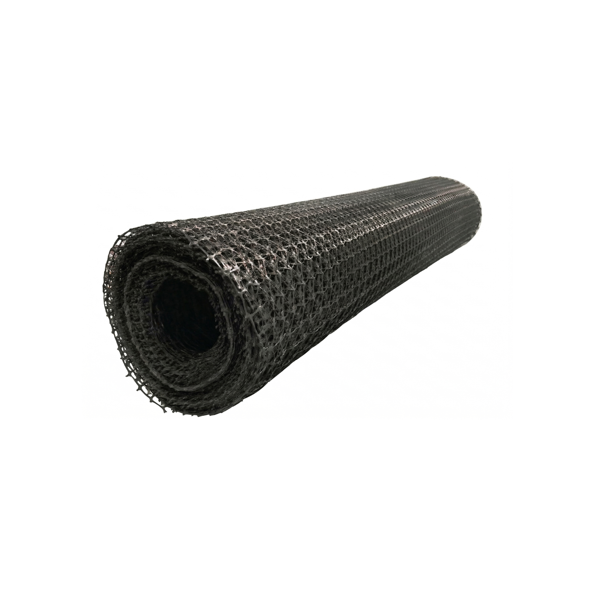
Product specifications
The triaxial polypropylene geogrid is offered in a single standard presentation of 3.95 m wide by 50 m long, with auditable strength of 10 kN/m per structural direction. The following table sets out the complete technical specifications of the only available variant:
| Specification | Value |
|---|---|
| SKU | 234123 |
| Material | Structural polypropylene (PP) |
| Orientation type | Triaxial (extended geometry in three directions) |
| Tensile strength | 10 kN/m (0.7 kip/ft) per structural direction |
| Aperture shape | Rigid triangular (0°, 60°, 120°) |
| Roll width | 3.95 m (13 ft) |
| Roll length | 50 m (164 ft) |
| Area per roll | 197.5 m² (2126 ft²) |
| Chemical resistance | Inert to acids, alkalis and soil microorganisms |
| Estimated service life | Decades under buried conditions |
| Main application | Subgrade reinforcement with multidirectional loads |
| Color | Black (with anti-UV carbon black additive) |
The companion guides for the biaxial PP geogrid and the uniaxial PP geogrid cover the other two orientations of the family: the biaxial is the standard lower-cost alternative for horizontal reinforcement over subgrades in reasonable condition, and the uniaxial is specifically designed for MSE walls and slopes (directional loads with low creep).
Step by step to use it
The following procedure covers the complete on-site installation cycle of the triaxial geogrid. Supervision by a geotechnical engineer or qualified site engineer is always recommended; the following instructions are indicative and do not replace the specific engineering design of each project.
Validation of the triaxial choice
The triaxial justifies its extra cost over the standard biaxial in specific scenarios: very soft subgrades (CBR less than 2), complex vehicular traffic with loads in multiple directions (parking areas, heavy equipment maneuvering platforms, road crossings), or pavements where backfill thickness is limited by elevation constraints. If your project does not fall into one of these cases, the biaxial does the job at lower cost. Before starting installation, validate with the site engineer that the triaxial choice corresponds to the real case of your project.
Subgrade preparation
Clean the surface of roots, large stones and vegetation. Level the subgrade (without potholes larger than 5 cm) and compact to the minimum density specified in the project. The triaxial is somewhat more tolerant of minor subgrade irregularities than the biaxial thanks to its geometry, but this does not exempt it from the requirement of correct foundation preparation. Avoid rolling out over water-saturated soil: if after rain the subgrade shows surface water, drain it or wait for it to partially dry.
Roll-out and overlap planning
The 3.95 m wide roll conditions the planning: for an 8 m wide platform, two rolls do not cover with margin as happens with the 6 m biaxial. Plan the layout ensuring that longitudinal joints are not aligned with the wheel ruts of the expected traffic. Deploy taut, without folds or wrinkles: the triangular apertures lose effectiveness when the grid is locally warped.
Overlap at joints considering the triaxial geometry
Minimum overlap of 30 cm at longitudinal joints and 50 cm at transverse joints, same as with biaxial. The operational difference is that with the triaxial geometry the overlap offers a more gradual load transition, so on very soft subgrades (CBR less than 1) the transverse overlap can be kept at 75 cm instead of the 100 cm that the biaxial would require. The rule of thumb that "if the subgrade sinks when stepped on, the overlap must be greater" still applies.
The triaxial benefits from combined use with nonwoven geotextile on subgrades with fines present. The combination of geotextile underneath plus triaxial on top creates a three-layer system (separation plus filtration plus reinforcement) that performs much better than any isolated element on problematic subgrades. The extra cost of the geotextile is justified by the additional saving in granular aggregate thickness that this combination allows. For swampy subgrades or those with CBR less than 1, this combined system is the recommended practice.
Backfill and compaction with optimization curves
Dump the aggregate without driving machinery over the exposed grid: keep at least 15 cm of aggregate between tracks or wheels and the geogrid. Compact in layers of 30 cm maximum. A particularity of the triaxial is that aggregate confinement is activated with fewer compaction passes than with biaxial: if your standard procedure requires 6 compactor passes, with triaxial you can start evaluating density at pass 4 and adjust additional passes based on the results. This optimization saves compaction time on large projects.
Do not assume that the triaxial is always better than the biaxial. The triaxial is more expensive and delivers real advantage in specific scenarios (very soft subgrades, multidirectional traffic, thickness constraints). On road projects with subgrade in good condition and conventional vehicular traffic, the 40 kN/m biaxial does the job more than adequately and the triaxial is over-dimensioning. The choice of geogrid should be based on the geotechnical report and the load analysis, not on the idea that more expensive is better.
Complementary products
To complement the triaxial geogrid in subgrade reinforcement works with complex vehicular traffic or soft soils, the following products cover the most common adjacent needs:
The biaxial PP geogrid is the standard alternative of the family: same structural function (horizontal reinforcement of subgrades) at lower cost, indicated when the subgrade is in reasonable condition and traffic is not extreme. The nonwoven PP geotextile complements the triaxial on subgrades with fines present: the combination of geotextile underneath plus triaxial on top offers a separation, filtration and reinforcement system that performs better than each isolated element. The metal rods serve for temporary anchoring of the geogrid during roll-out and verification of non-displacement when machinery passes with backfill. The uniaxial PP geogrid is a solution for a different problem (MSE walls, slopes) and does not replace the triaxial in subgrade reinforcement.
Maintenance and care
The triaxial geogrid buried under a layer of aggregate and pavement requires no maintenance during its service life of decades. The relevant care is storage prior to installation: rolls in a horizontal position, on a clean surface, covered against direct sunlight. Although the PP carries an anti-UV additive, prolonged storage in the sun degrades the surface properties and would compromise the interlock with the aggregate.
During on-site handling, a particularity of the triaxial is that the roll format (3.95 m wide) makes it more sensitive to accidental transverse bending —a roll resting on a stone during storage can generate a permanent fold that affects subsequent roll-out—. Always store the rolls on flat pallets or a smooth bed. Visually inspect each roll before lowering it to the site to identify folds, cuts or edge damage that may have occurred during transport and unloading.
Frequently asked questions (FAQ)
When does the extra cost of triaxial vs biaxial pay off?
The triaxial fulfills its differential function in three specific scenarios: very soft subgrades (CBR less than 2) where the standard biaxial does not deliver sufficient performance; complex vehicular traffic with loads in multiple directions (crossings, maneuvering platforms, commercial parking areas with crossing flows); projects where backfill thickness is limited by elevation constraints or excavation cost. On conventional road projects over subgrade in good condition, the biaxial is sufficient and more economical.
How do I calculate how many rolls I need if the roll width is 3.95 m?
Calculate the effective covered width by deducting the lateral overlap (0.30 m per joint). For an 8 m wide platform with two parallel rolls, the effective covered width is 3.95 m plus 3.65 m (3.95 minus 0.30 of overlap) equal to 7.60 m, which leaves 0.40 m uncovered; you will need a third partial roll. For large areas, the layout planning of the roll-out has a significant impact on consumption: a small optimization of the roll arrangement can save one or two whole rolls. It is worth making a preliminary layout sketch before ordering the material.
Can the triaxial be used in MSE walls instead of uniaxial?
No. The triaxial is optimized for omnidirectional confinement of aggregate in the horizontal plane, not for the sustained directional strength that MSE walls require. The declared strength of the triaxial (10 kN/m per direction) is much lower than that of the uniaxial (80 kN/m on the strong axis), and its creep behavior under sustained load is not calibrated for structural walls. Use uniaxial where the project calls for MSE walls, reinforced slopes or abutments.