If you are building a multi-meter mechanically stabilized earth (MSE) retaining wall, a steep slope, or a bridge abutment that withstands the backfill thrust for decades, the uniaxial geogrid is the structural component that prevents collapse from accumulated creep under sustained load. This MOLTEXO uniaxial PP geogrid delivers 80 kN/m of directional strength with low creep, in a 3 m × 100 m roll, a dimension calibrated for typical MSE walls in road and urban development.
Installing a uniaxial geogrid is NOT comparable to installing a biaxial one: the procedure requires prior structural engineering design (it is not optional), strict control of roll orientation (the strong axis must be perpendicular to the wall face), and a precise layer-by-layer placement sequence with compaction between each one. This guide covers the on-site operating procedure, NOT the structural sizing —the calculation of wall height, layer spacing, and geogrid length per layer must always come from the responsible designer—.
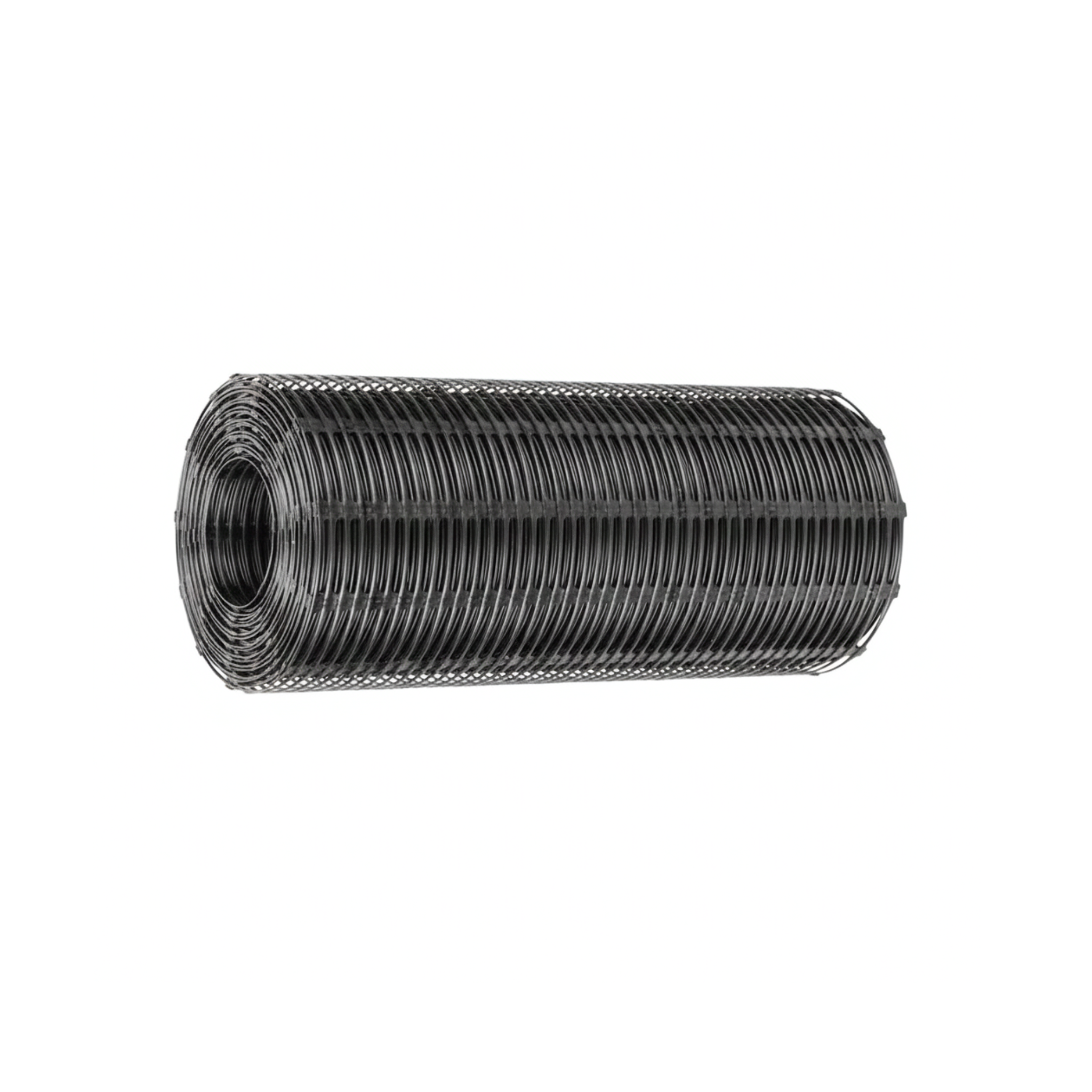
Product specifications
The polypropylene uniaxial geogrid is offered in a single standard presentation of 3 m wide by 100 m long, with an auditable directional strength of 80 kN/m in the roll direction. The following table sets out the complete technical specifications of the only available variant:
| Specification | Value |
|---|---|
| SKU | 654761 |
| Material | Mono-oriented stretched polypropylene (PP) |
| Orientation type | Uniaxial (stretched in one direction) |
| Tensile strength | 80 kN/m (5.5 kip/ft) in the roll direction |
| Creep resistance | Low, calibrated for long-duration MSE walls |
| Roll width | 3 m (9.8 ft) |
| Roll length | 100 m (328 ft) |
| Area per roll | 300 m² (3229 ft²) |
| Chemical resistance | Inert to acids, alkalis, and soil microorganisms |
| Estimated service life | Decades under buried conditions |
| Main application | MSE walls, reinforced slopes, abutments |
| Color | Black (with anti-UV carbon black additive) |
The sister guides for the biaxial PP geogrid and the triaxial PP geogrid cover the other two orientations in the family, specifically designed for horizontal reinforcement of road bases and subgrades —a different structural task from that of MSE walls—.
Step-by-step on how to use it
The following procedure covers the on-site operating cycle: from verification of the structural design through to layer-by-layer backfilling with compaction. The supervision of a structural engineer or qualified resident engineer is always mandatory on MSE walls and retaining works; the following indications are operational guidance and do not replace the engineering design specific to each project.
Verification of the structural design and setting out
Before any fieldwork, confirm with the project engineer: the height of the wall or slope, the vertical spacing between geogrid layers, the horizontal length of each geogrid layer (which defines the “interlock” in the backfill), and the type of approved granular or cohesive backfill. Without this prior design, the installation is blind construction and compromises structural safety. Set out the base of the wall and verify the leveling of the foundation.
Preparation of the foundation and first layer
Excavate down to foundation level according to the design. Compact the bottom to the specified minimum density. Place the first layer of granular backfill and compact it. Mark on the backfill the line where the visible wall face will be placed (concrete blocks, gabions, formed earth bags, whatever the project specifies). The first geogrid roll is laid out over this layer.
Laying out the roll with the correct orientation
Unroll the roll so that the LONGITUDINAL DIRECTION OF THE ROLL IS PERPENDICULAR TO THE WALL FACE. This is critical: the 80 kN/m strength is only on the longitudinal axis of the roll. If you lay the roll parallel to the face, the net ends up on the weak axis and the wall collapses progressively. Visually mark the roll direction on site (with paint on the ground, for example) to avoid operator errors in subsequent layers.
Anchoring at the face and overlap between rolls
The extension of the roll must reach the wall face (blocks or facing system) and “wrap” the front as indicated by the project detail. At the face, the net is anchored by the weight of the upper backfill and by mechanisms specific to the facing system. If you need several rolls in a single layer to cover the length of the wall, overlap transversally (parallel to the face) a minimum of 50 cm —but NEVER overlap longitudinally (perpendicular to the face), because that cuts the strong axis of the net—. If the length of the roll is not enough to cover the length of the wall, individual cuts are required with a vertical offset of the joint between layers.
On tall MSE walls where the geogrid is arranged in many layers, mark each roll on site with the layer number before laying it out (with paint, site tape). The visual control of which layer corresponds to which avoids orientation errors and allows the resident engineer to audit progress without reviewing the drawing daily. Once covered by backfill, there is no way to inspect the position of the lower layers: traceability must be built during execution.
Layer-by-layer backfilling and compaction
Place the next layer of granular backfill over the laid-out geogrid. Dump the material from the inside toward the exterior of the wall (NEVER from the front toward the back, because it would push the net and compromise its anchoring at the face). Compact each layer to the specified Proctor percentage before laying out the next geogrid layer. The vertical spacing between geogrid layers comes from the design —typically between 30 cm and 60 cm depending on the total height of the wall—.
Do not install uniaxial geogrid with the roll direction parallel to the wall face. It is the most expensive and most common mistake on inexperienced job sites: the net is loaded on the weak axis (typically between 5 and 10 kN/m of transverse strength instead of the 80 kN/m of the strong axis) and the wall deforms progressively over months or years until collapse. Detection on site is visual: look at the nodes of the net; the long “fluid” pattern in the roll direction is the strong axis and must be perpendicular to the wall face.
Complementary products
To complement the uniaxial geogrid in MSE walls, slopes, and retaining works, the following products cover the most common adjacent needs:
The biaxial PP geogrid is the specific solution for horizontal reinforcement of road bases and industrial platforms: a different structural task, it is not an alternative to the uniaxial but a complement in integrated projects. The woven PP geotextile is used in MSE walls as a separation layer between the granular backfill and the natural soil, preventing contamination by fines in draining systems. The metal rods are useful as a temporary anchor during laying out and visual verification of the correct orientation before backfilling. The triaxial PP geogrid is a solution for different problems (soft subgrades with complex traffic) and does not replace the uniaxial in MSE walls.
Maintenance and care
The uniaxial geogrid buried in MSE walls requires no maintenance during its service life. What does require monitoring is the behavior of the wall: on structural walls (especially those of significant height), it is advisable to establish a program of periodic visual inspection of the external face to detect signs of progressive deformation, localized bulging, cracks in block joints, or differential settlement at the crown. These signs may indicate that something is not right internally, well before collapse. Visual inspection every 6 months during the first 5 years of life is good practice.
For storage prior to installation, keep the rolls in a horizontal position, on a clean surface, covered against direct sunlight. The uniaxial geogrid is more susceptible to mechanical damage at the edges than the biaxial: a blow against a stone during unloading can start a tear that propagates as it is unrolled. Visually inspect each roll before lowering it to the job site and before laying it out, especially the first and last meters that may have been exposed during transport.
Frequently asked questions (FAQ)
Why can’t I use uniaxial where the project calls for biaxial?
The uniaxial geogrid has very low strength on the transverse axis (perpendicular to the roll), typically between 5 and 10 kN/m. If you use it on a road base where vehicle loads come from any direction, the weak axis is loaded and the net provides no reinforcement in part of the plan. The uniaxial is optimized for situations where the tractive force goes in a single known direction (perpendicular to a wall face). For bidirectional reinforcement of subgrades use biaxial; for multidirectional with complex traffic, triaxial.
What do I do if the length of the roll is not enough to cover the wall from end to end?
The horizontal length of each layer comes from the structural design (typically between 0.7 and 1.0 times the height of the wall). If the length of the wall exceeds the 100 meters of the roll, several sections per layer are required with a transverse overlap of 50 cm as a minimum (parallel to the face). NEVER overlap longitudinally because that cuts the strong axis. To coordinate the joints between layers, offset each layer at least 1 meter relative to the previous one to avoid continuous planes of weakness.
Can I use uniaxial geogrid to reinforce an existing slope at risk of sliding?
Yes, it is one of the typical uses. The installation involves excavation, laying out geogrid layers with compacted backfill, and reconstruction of the slope with a more stable geometry. This intervention ALWAYS requires prior geotechnical engineering design that evaluates potential failure planes, the properties of the existing soil, and the upper load. The correct installation of geogrid on a problematic slope can prevent a slide; the incorrect one can accelerate it by giving the user a false sense of security.